The potential difference across a resistor is a crucial parameter in electrical circuits, as it determines the energy transfer from one point to another. It is directly proportional to the current flowing through the resistor, which means that if the current increases, the potential difference will also increase.
The relationship between current and potential difference is described by Ohm’s Law. This relationship forms the foundation of circuit analysis and is widely used in electrical engineering and physics. The law is named after Georg Simon Ohm, a German physicist who first formulated it in 1827.
Ohm’s Law is a fundamental principle that is essential for understanding electrical circuits. By understanding the relationship between potential difference, current, and resistance, you can analyze the behavior of electrical circuits and predict the response of circuits to changes in the current or potential difference. This knowledge is important for solving circuit analysis problems, designing electrical circuits, and interpreting data from experiments.
Aim
To investigate the dependence of potential difference across a resistor on current and to verify Ohm’s Law.
Theory
What is Ohm’s Law?
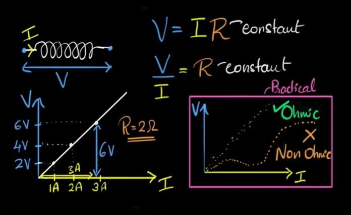
Ohm’s Law states that the current flowing through a conductor between two points is directly proportional to the voltage across the two points, and inversely proportional to the resistance between them. Mathematically, it can be expressed as:
Where,
R is constant of proportionality and is known as resistance
V is potential difference
I is the current
What Factors Affect Resistance?
- Nature of the resistor.
- As the length of the wire increases, the resistance also increases. This means that resistance is directly proportional to the length of the wire.
- An increase in the cross-sectional area of the wire leads to a decrease in its resistance. This means that resistance is inversely proportional to the cross-sectional area of the wire.
Materials Required
- Resistor
- Ammeter
- Voltmeter
- Power supply
- Wires
- Connecting leads
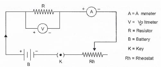
Circuit Diagram
A power supply is connected to the resistor in series with an ammeter and a voltmeter. The ammeter is used to measure the current, while the voltmeter is used to measure the potential difference across the resistor.

Procedure
- Assemble the required equipment as per the circuit diagram provided.
- Connect all the components in the circuit using connecting wires while keeping the key switch in the open position.
- Connect the positive terminal of the battery to the positive terminal of the ammeter.
- Before connecting the voltmeter, make sure to identify its positive and negative terminals.
- Once the circuit is connected, take readings of both ammeter and voltmeter and adjust the rheostat as needed by turning on the key switch.
- Obtain three different sets of current and voltage readings using the slider control.
- Record the readings in the observation table.
- Calculate the resistance using the formula .
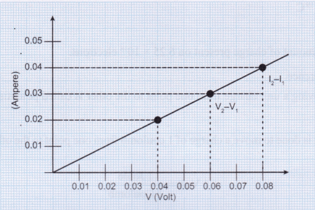
- Plot a graph with voltage (V) on the x-axis and current (I) on the y-axis to illustrate the relationship between the two values.
10. Keep in mind that the resistance of pure metals increases as the temperature increases.
Observation Table
A. Least Count and Range of Voltometer and Ammeter
| Voltometer | Ammeter | |
|---|---|---|
| Range | 0 – 0.1 V | 0-0.5 A |
| Least Count | 0.01 V | 0.01 A |
B. Readings of Voltmeter and Ammeter
| S.No. | Potential Difference (V) | Current (I) | Resistance |
|---|---|---|---|
| 1. | 0.04 V | 0.02 A | 2Ω |
| 2. | 0.06 V | 0.03 A | 2Ω |
| 3. | 0.08 V | 0.04 A | 2Ω |
Calculation
Mean value of Resistance:
Graph
Plot a graph of potential difference against current, with the potential difference on the y-axis and the current on the x-axis.

Precautions
- Ensure that the ammeter and voltmeter are properly connected in series and in the correct direction.
- Ensure that the power supply is adjusted gradually to avoid any sudden change in current
- Use thick copper wires that have had their insulation stripped using sandpaper as connecting wires.
- The connections need to be tight to prevent outside resistance.
- Before conducting the experiment, the connections must follow the circuit schematic and have the teacher’s approval.
- The resistor should be connected in series with the current, which should enter the ammeter from the positive terminal and exit from the negative terminal.
- Voltmeter and resistor need to be linked in parallel.
- It is important to accurately record the ammeter and voltmeter least count.
- The ammeter and voltmeter’s points should be at zero when there is no current flowing.
- The current should only flow for a brief period of time to prevent the circuit from heating up unnecessarily.
Recommended Articles:
DARCY’S LAW: Introduction, Equation, Application, Properties, And Limitation
The Dark side of the moon
Davisson Germer Experiment: History, Set up, Observations, And Relation
Dc Generator: Introduction, Parts, Work, Equation, Losses, Types, & Applications
Read All About Density of Air
