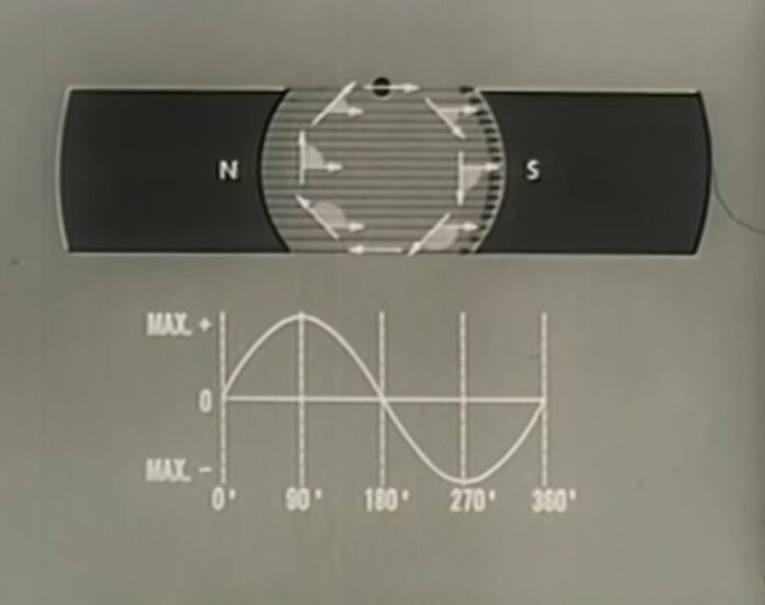
A direct-current (DC) generator is a rotating machine that supplies an electrical output with unidirectional voltage and current. The basic principles of operation are the same as those for synchronous generators. Voltage is induced in coils by the rate of change of the magnetic field through the coils as the machine rotates. This induced voltage is inherently alternating in form since the coil flux increases and then decreases, with a zero average value.
The field is produced by direct current in field coils or by permanent magnets on the stator. The output, or armature, windings are placed in slots in the cylindrical iron rotor. A simplified machine with only one rotor coil is shown in Figure 6. The rotor is fitted with a mechanical rotating switch, or commutator, that connects the rotor coil to the stationary output terminals through carbon brushes. This commutator reverses the connections at the two instants in each rotation when the rate of change of flux in the coil is zero—i.e., when the enclosed flux is maximum (positive) or minimum (negative). The output voltage is then unidirectional but is pulsating for the simple case of one rotor coil. In practical 2-pole machines, the rotor contains many coils symmetrically arranged in slots around the periphery and all connected in series. Each coil is connected to a segment on a multi-bar commutator. In this way, the output voltage consists of the sum of the induced voltages in a number of individual coils displaced around half the periphery. The magnitude of the output voltage is then approximately constant, containing only a small ripple. The voltage magnitude is proportional to the rotor speed and the magnetic flux. Control of output voltage is normally provided by control of the direct current in the field.
For convenience in design, direct-current generators are usually constructed with four to eight field poles, partly to shorten the end connections on the rotor coils and partly to reduce the amount of magnetic iron needed in the stator. The number of stationary brushes bearing on the rotating commutator is usually equal to the number of poles but may be only two in some designs.
Direct-current generators were widely used prior to the availability of economical rectifier systems supplied by alternators. For example, they were commonly employed for charging batteries and for electrolytic systems. In some applications, the direct-current generator retains an advantage over the alternator-rectifier in that it can operate as a motor as well, reversing the direction of power flow. An alternator, by contrast, must be fitted with a more complex rectifier-inverter system to accomplish power reversal.
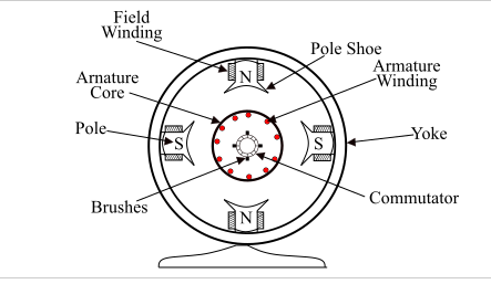
Parts of a DC Generator
A DC generator can also be used as a DC motor without changing its construction. Therefore, a DC motor, otherwise a DC generator, can be generally called a DC machine. Below we have mentioned the essential parts of a DC Generator.

Stator – A stator is a set of two magnets placed in such a way that opposite polarity faces each other. The purpose of the stator is to provide a magnetic field in the region where the coil spins.
Rotor – A rotor is a cylindrical laminated armature core with slots. Armature Core – The armature core is cylindrical in shape and has grooves on the outer surface. These slots accommodate armature winding in it.
Armature Winding – These are the insulated conductors placed in the armature core. Because of them, the actual conversion of power takes place.
Field Coils – To produce the magnetic field, field coils are placed over the pole core. The field coils of all the poles are connected in series. When current flows through them, adjacent poles acquire opposite polarity.
Yoke – The outer hollow cylindrical structure is known as Yoke. It provides support to main poles and inter poles and gives a low reluctance path for the magnetic flux.
Poles – The main function of the poles is to support the field coils. It increases the cross-sectional area of the magnetic circuit, which results in a uniform spread of magnetic flux.
Pole Shoe – To protect the field coil from falling and to enhance the uniform spread of magnetic flux pole shoe is used. The pole shoe is fixed to Yoke.
Commutator – The commutator is cylindrical in shape. Several wedge-shaped, hard drawn copper segments form a commutator.
The functions of a commutator is to connect stationary external circuits to the rotating armature conductors through brushes and to convert induced alternating current into direct current.
Working Principle of a DC Generator:
A DC generator operates on the principle of Faraday’s laws of electromagnetic induction. According to Faraday’s law, whenever a conductor is placed in a fluctuating magnetic field (or when a conductor is moved in a magnetic field) an EMF is induced in the conductor. (Image will be Uploaded soon)If the conductor is guided with a closed path, the current will get induced. The direction of the induced current (given by Fleming’s right-hand rule) changes as the direction of movement of the conductor changes.For example, consider the case, an armature rotating in clockwise direction and conductor at the left moving in an upward direction. As the armature completes its half rotation the direction of movement of the conductor will get reversed downward. The direction of the current will be alternating. As the connections of armature conductors get reversed, a current reversal takes place. Thus, we get unidirectional current at the terminals
.
EMF Equation of a DC Generator:
The EMF equation for DC generator is expressed as:
Where,
Eg – Generated EMF across any parallel path
P – Total number of poles in the field
N – Rotational speed of armature(rpm)
Z – Total number of armature conductors in the field.
Ø- Magnetic flux produced per pole
.A – number of parallel paths in the armature.
Losses in DC Generators
While converting the mechanical energy into electrical energy, there are losses of energy i.e. whole input isn’t converted into output. These losses are classified into mainly three types:
Copper Loss- These losses occur while current flows through windings and are of three types: armature copper loss, field copper winding loss and losses because of brush resistances.
Iron Losses- Due to the induction of current in the armature, eddy current losses and hysteresis loss occur. These losses are also called Core losses or Magnetic losses.
Mechanical Losses- Losses which occur because of friction between the parts of the generator are called mechanical losses.
Types of DC Generators:
The three types of self-excited DC generators are:
Series Wound Generators.
Shunt Wound Generators.
Compound Wound Generators.
Applications of DC Generators:
Applications of DC generators are as follows:
- The separately excited type DC generator is used for power and lighting purposes using the field regulators.
- The series DC generator is used in arc lamps for stable current generator, lighting and booster.
- Level compound DC generators are used to supply power to hostels, offices, lodges.
- Compound DC generators are used for supplying power to DC welding machines.
- A DC generator is used to compensate for the voltage drop in the feeders.
Recommended Articles:
D’alembert’s Principle: Introduction, Derivation, Examples, And Applications
Darcy Weisbach Equation Derivation
DARCY’S LAW: Introduction, Equation, Application, Properties, And Limitation
The Dark side of the moon
Davisson Germer Experiment: History, Set up, Observations, And Relation
A DC generator is an electrical machine whose main function is to convert mechanical energy into electricity. Types of generators are: AC generators DC generators Dc Generator FAQs
What is a DC generator?
What are the types of generators?
