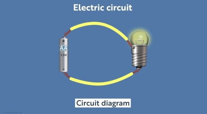
An electric circuit is a path for transmitting electric current i.e., I. A circuit diagram (also known as an electrical diagram, elementary diagram, wiring diagram, or electronic design) is a diagram that shows how an electrical circuit works. A graphical circuit diagram employs basic depictions of parts, whereas a schematic diagram uses specified symbolic representations to show the circuit’s components and their relationships.
What is Circuit?
In 1880, Alessandro Volta invented the first electric circuit. It can be defined as a closed path of wires and electrical components that allows a current through it on the application of potential difference between two points in the path. An electric circuit includes a device that gives energy to the charged particles constituting the current, such as a generator or a battery; devices that use current, such as electric motors, lamps, or computers; and the connecting wires or transmission lines.
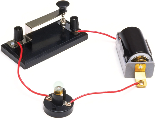
What is a circuit Diagram?
A circuit diagram is a simple representation of the components of an electrical circuit using either the standard symbols or the image of various parts. It shows the relative positions of all the elements and their connections to one another in the circuit. It is often used to visually represent the circuit and helps the electrician in many ways.
Types of Electric Circuits
There are five types of the electric circuit:
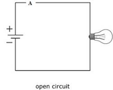
Open Circuit: When there is a faulty electrical component or wire in a circuit or the switch is OFF and not ON, then it is called an Open Circuit. In the below diagram, we can see that the Bulb is Not glowing because either the switch is OFF or there is a fault in the electrical wire or any of the components.
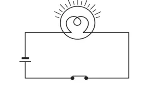
Closed Circuit: When the load works on its own in an electric circuit then the given circuit is called Close Circuit or Closed Circuit. Under this situation, the current flow’s value depends on the circuit’s load.
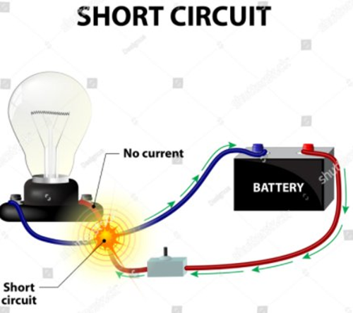
Short Circuit: When both points or we can say terminals i.e., positive and negative (+ & –) of the voltage source in a circuit get joined with each other for some reason then it is called a Short Circuit. Maximum electric current starts to flow under this situation. The short circuit generally happens when the conducting electrical wires get joint of even because of shorting in the load in the circuit.
Parallel Circuit: When 2 or more loads (Bulb, LED, CFL, Fan, etc) are connected to each other in parallel, then it is called Parallel Circuit. In this circuit, the voltage capacity of all loads must be equal to the input supply in the circuit. The power of “load” can be different in this circuit. In a parallel circuit, if one load or LED or bulb gets fused, then the rest of the bulbs will still get a power supply and will glow or all other LEDs will work.

Series Circuit:
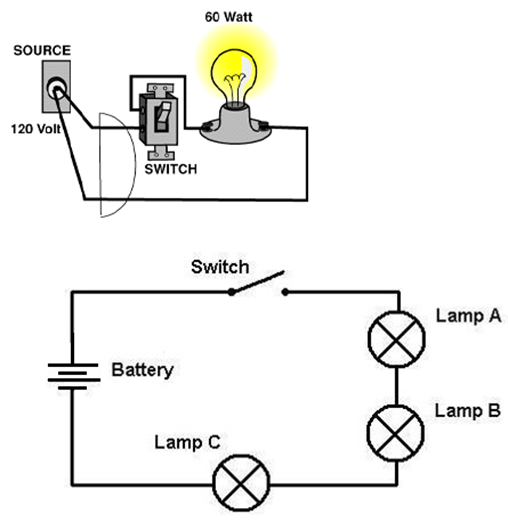
When 2 or more loads (Bulb, LED, CFL Fan, etc) are connected to each other in a series, then it is called a Series Circuit. In a series circuit, if one load or LED or bulb gets fused, then the rest of the bulbs will not get a power supply and will not glow or the rest of the LEDs will not work.
Components of Electric Circuit and symbols
Following the components of the electric circuit
Battery: A battery is a device that converts chemical energy contained within its active substances directly into electric energy by means of an electrochemical oxidation-reduction i.e., redox reaction.
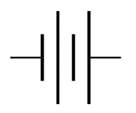
An electric cell: An electric cell is a device to convert chemical energy into electrical energy and has two terminals, which are made up of metal: one terminal is positive while the other one is negative.

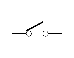
Switch: A switch is a component of an electric circuit that response to an external force to change an electric signal mechanically.
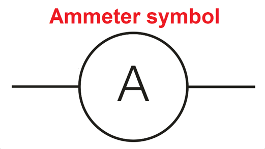
Ammeter: An ammeter is an instrument for measuring either direct current i.e., DC or alternating electric current i.e., AC, in amperes.
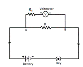
Voltmeter: A voltmeter is an electrical device that measures voltages of direct current or alternating current on a scale commonly in millivolts, volts or kilovolts.
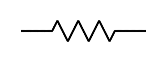
Resistor: The electrical resistor is a passive electrical component that creates resistance in the flow of electric current i.e., it hinders the flow of current.
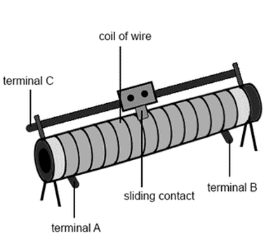
Variable resistance or Rheostat: Rheostat or the variable resistance, is used to regulate the amount of current flow by increasing or decreasing the resistance to the current flow.
Recommended Articles:
Charge Transfer: Mechanism, Types, and Applications
Understanding of Charged Plane Sphere
Charging by Induction: Introduction, Importance, and Applications
Cherenkov Radiations: Introduction, Properties, Effect And Uses
Circuit Component: Active, Source, Transistor, and Components
The electrical resistor is a passive electrical component that creates resistance in the flow of electric current i.e., it hinders the flow of current. In 1954, the first digital voltmeter was invented and produced by Andrew Kay of Non-Linear Systems, a voltmeter is an electrical device that measures voltages of direct current or alternating current on a scale commonly in millivolts, volts, or kilovolts. An ammeter is an instrument for measuring either direct current i.e., DC, or alternating electric current i.e., AC, in amperes. An electric circuit is a path for transmitting electric current i.e., I. Circuit Diagram FAQs
Define Resistor
Who discovered the voltmeter?
What is an Ammeter?
Define an electric circuit.
